Module 1 Formstorming
Connect: Circuits and Interaction
Mia Weber
Project 1
Module 1
Activity 1


Activity 2


Project 1
Final Project 1 Design
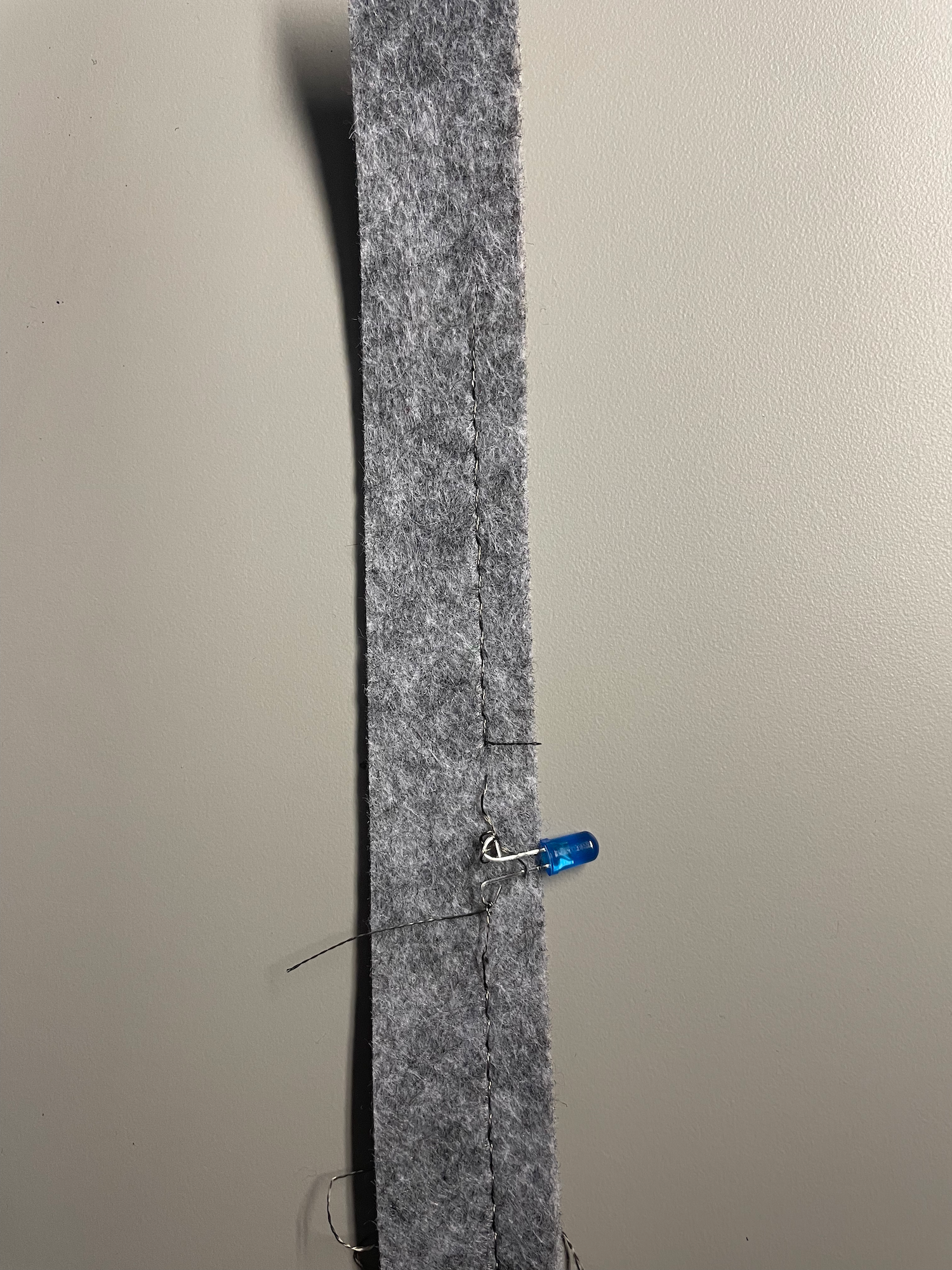
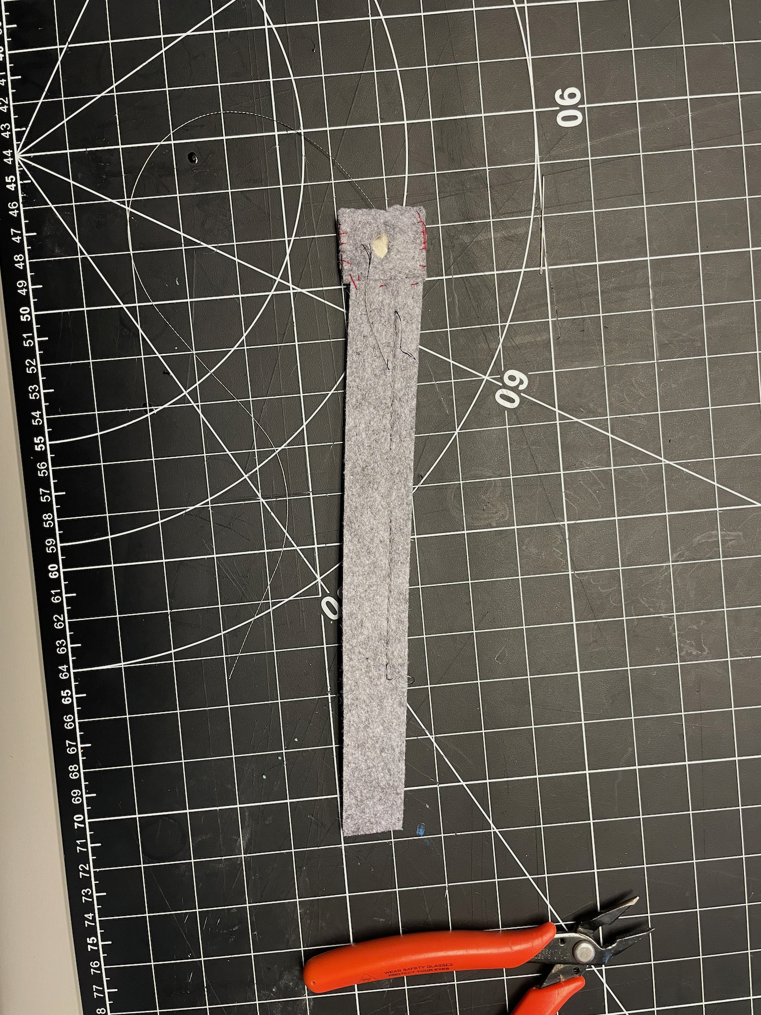
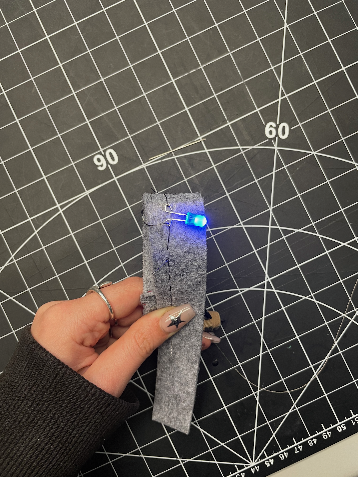
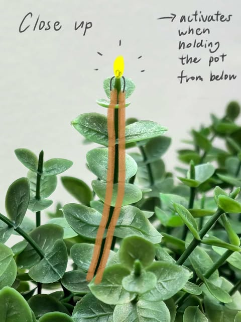
Wearable Interactive Affordance Based Circuit

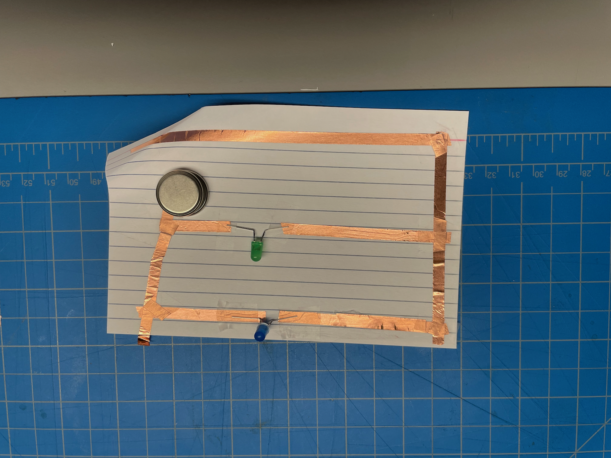
Non-Wearable Interactive Affordance Based Circuit
